Applications

Energy & Power
HVAC

Data Center

Pool

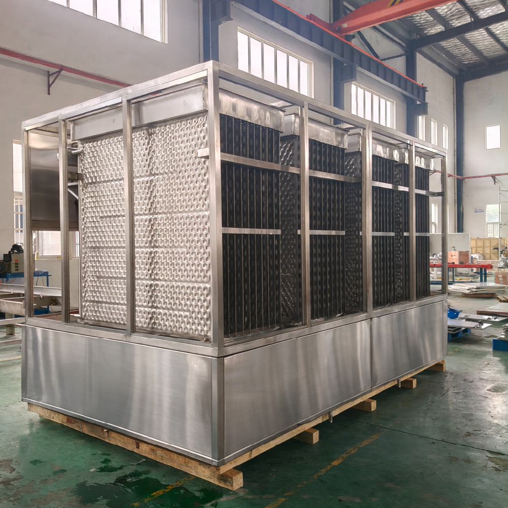
Refrigeration

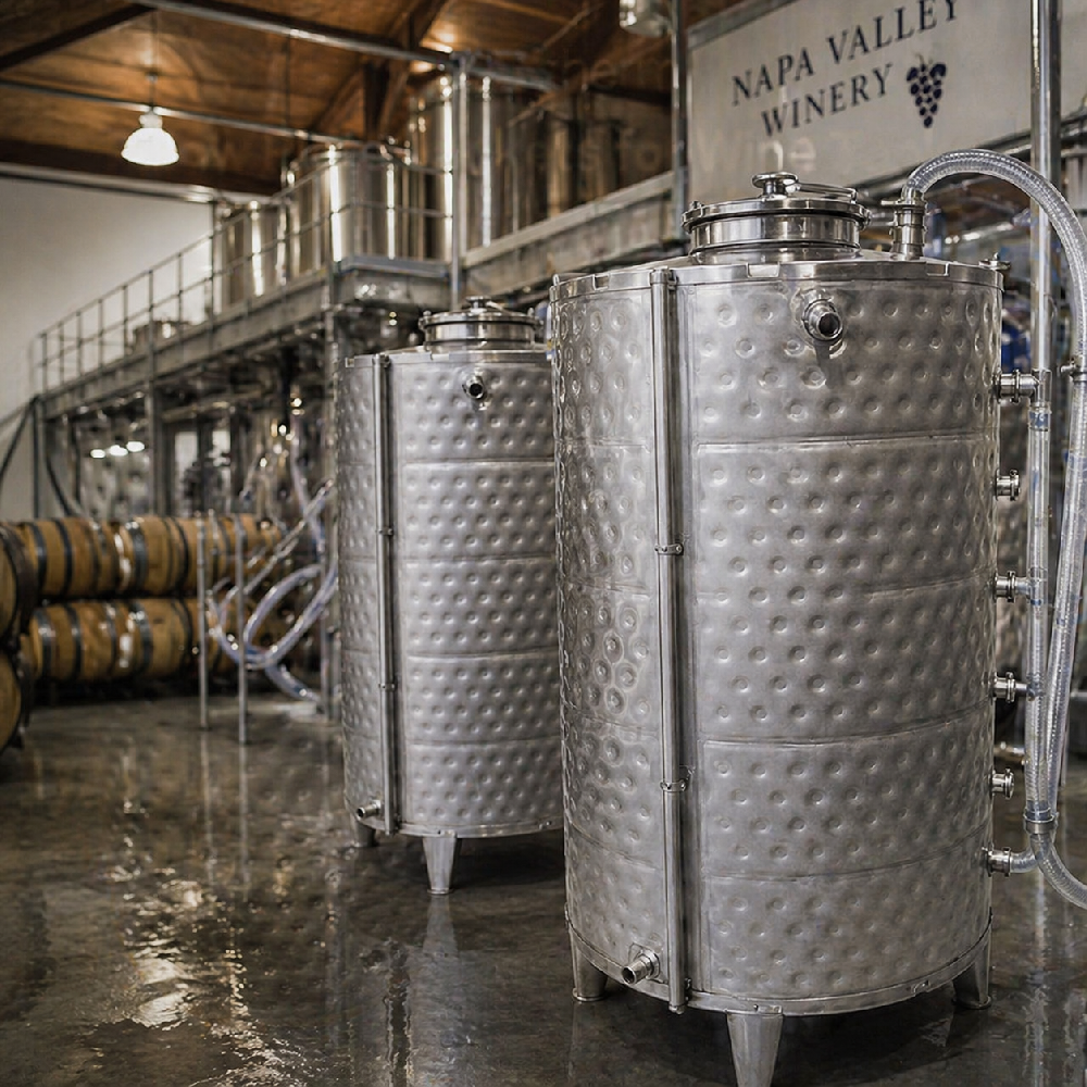
Food & Beverage

Transportation & Marine

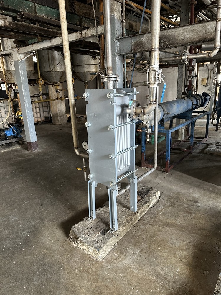
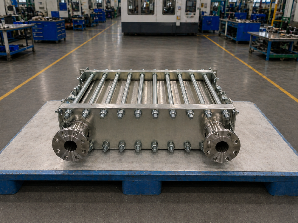
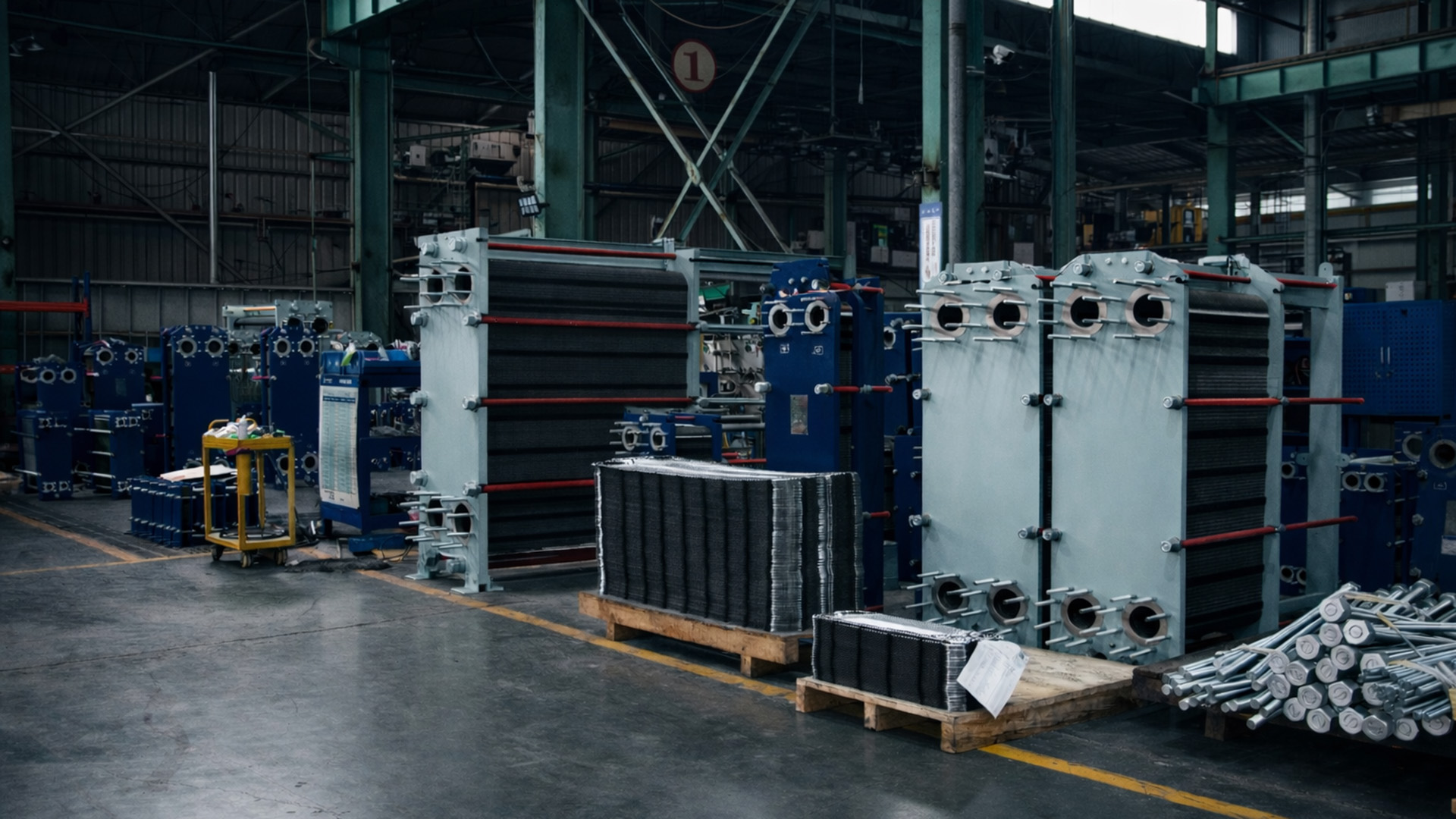
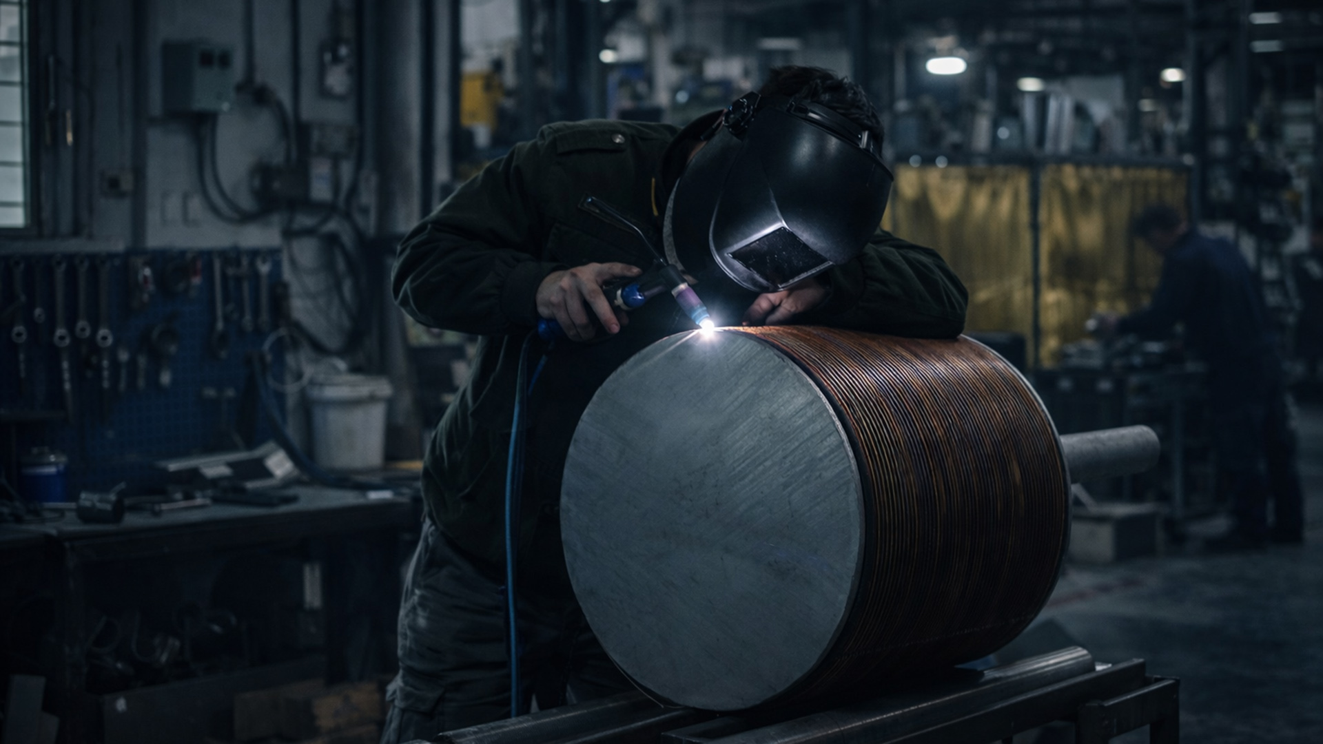
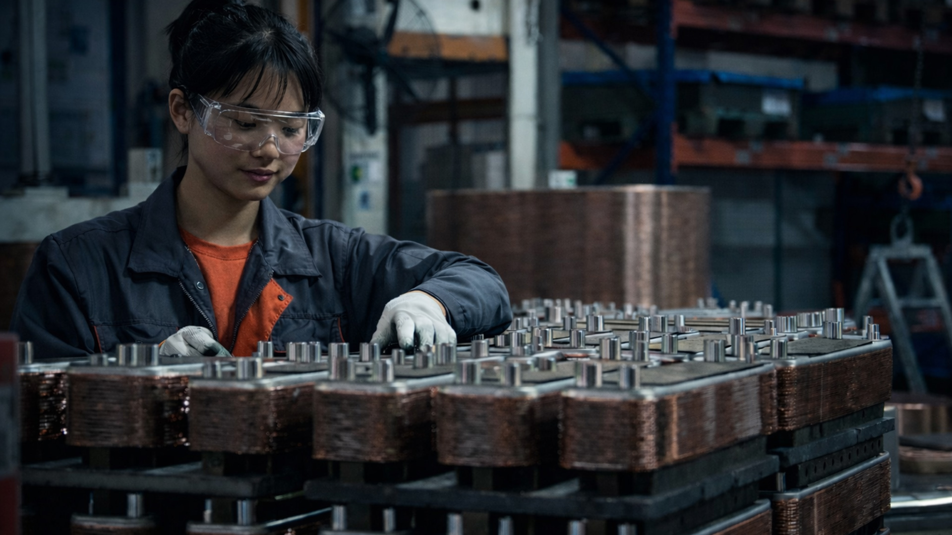
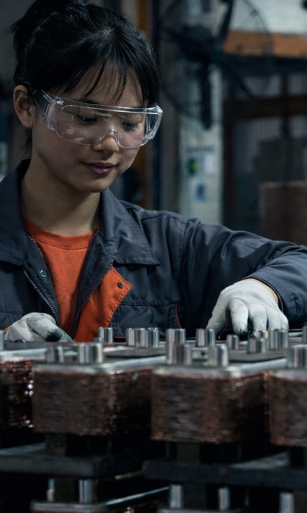
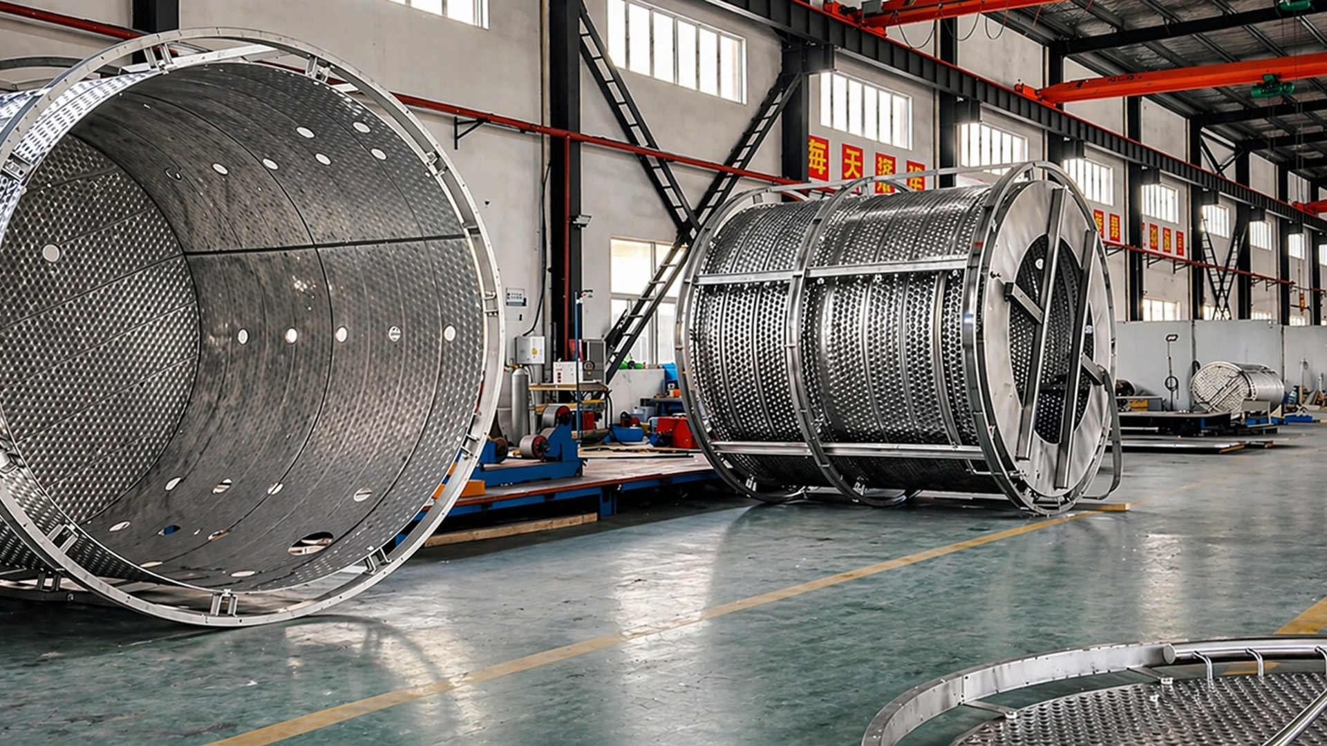
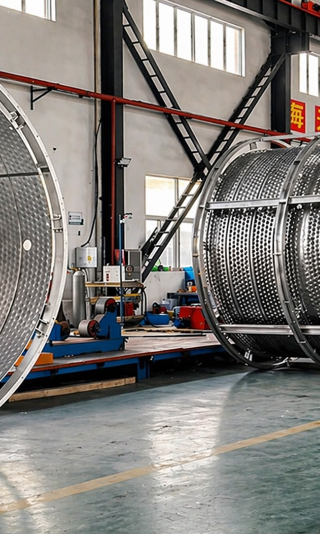
Industrial & Manufacturing


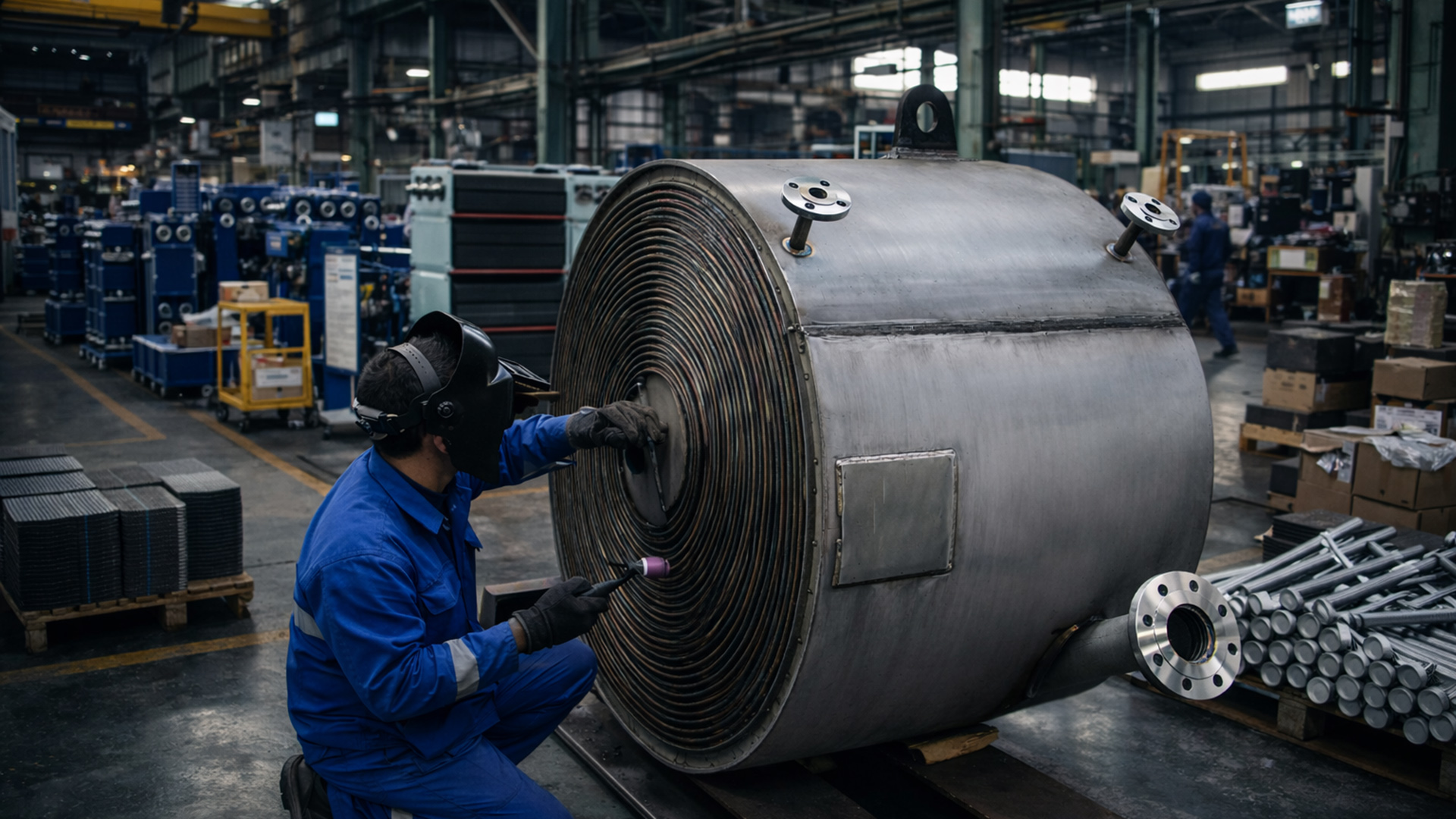
Innovation in Engineering
We develop smarter, leaner solutions.
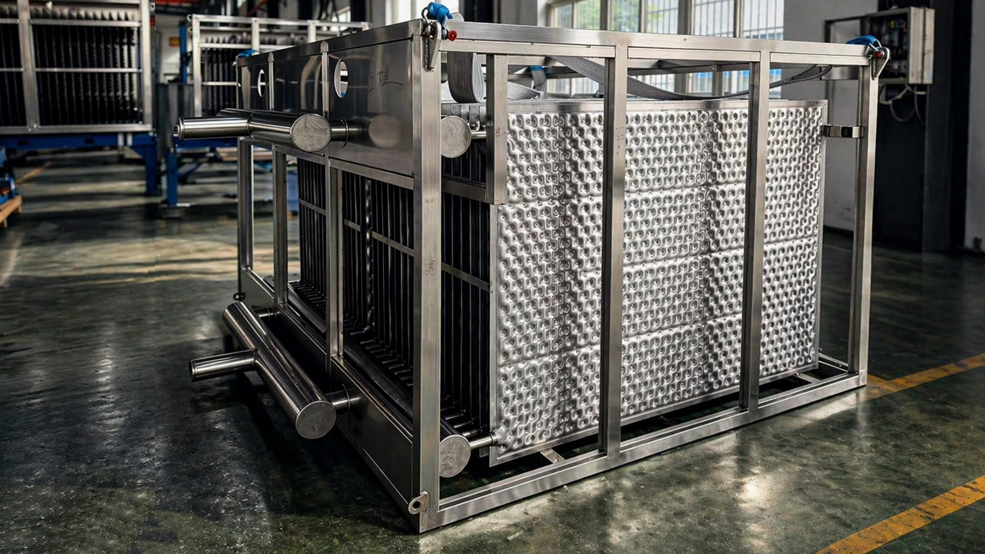
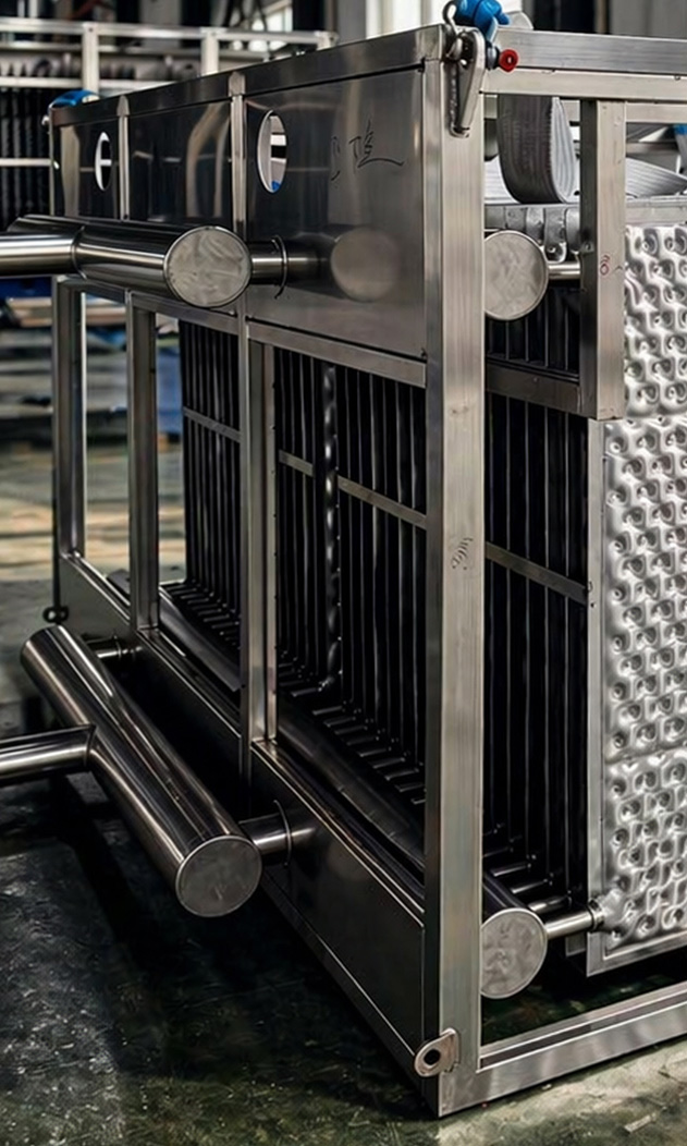
We constantly explore new materials, geometries, and thermal designs to optimize performance, durability, and cost-efficiency in every exchanger we deliver.

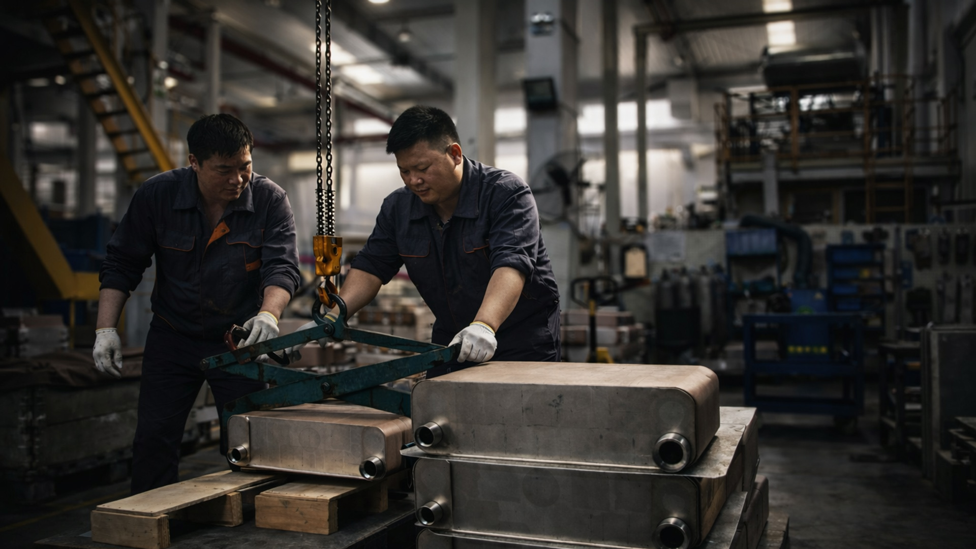
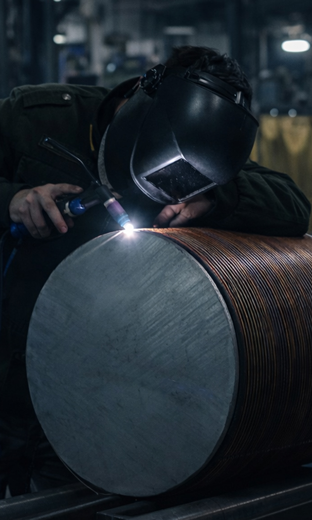
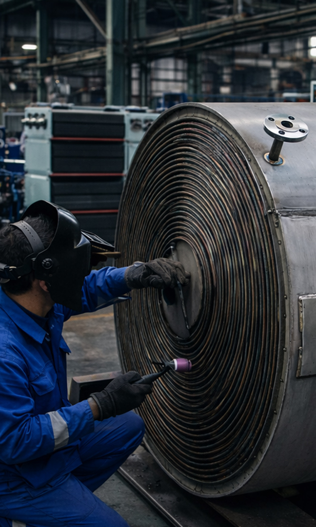
Guaranteed Quality
Every unit is tested, every detail matters.
All exchangers are subject to rigorous pressure testing, leak detection, and dimensional control — ensuring reliable performance under real-world conditions.

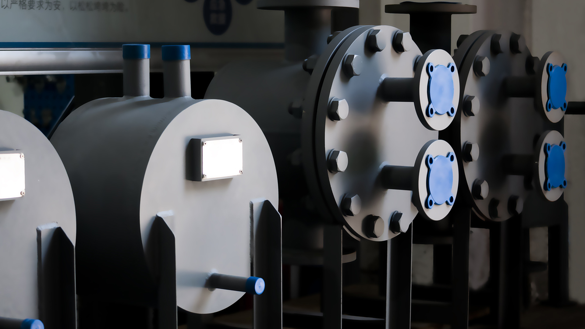
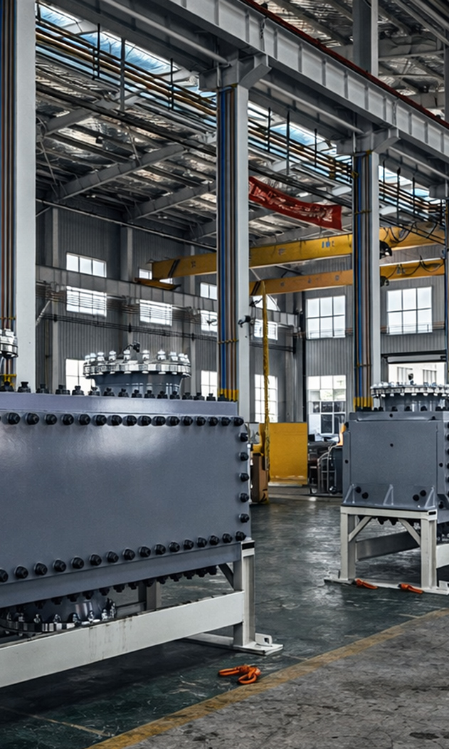
Technical Expertise
We don’t just supply — we help you design it right.
From media compatibility to thermal sizing and layout optimization, our engineering team supports you in choosing the right exchanger for your specific process.

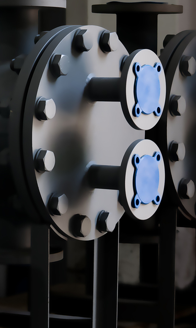
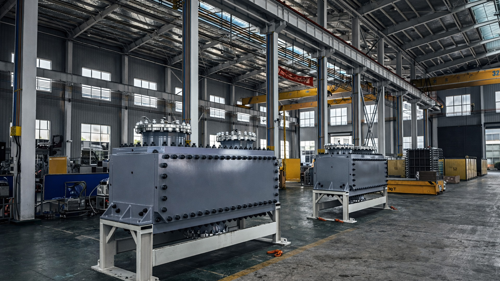
Trusted Partnerships
We collaborate with certified manufacturers and global suppliers.
By working only with ISO-certified partners and material suppliers, we ensure consistent quality across all HEXNOVAS-labeled equipment.